Reset and clock control (RCC) of STM32
tags: STM32 self-study notes stm32 Single-chip microcomputer Embedded
First, reset
The STM32 reset circuit is shown in the figure: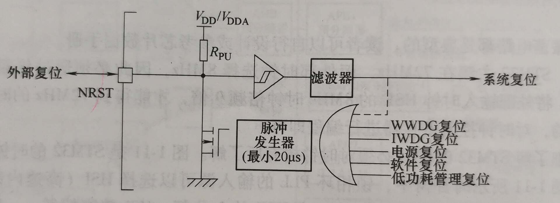
Reset is divided into three forms, namely power reset, system reset, and backup area reset.
When the system is powered on, power down, and when returned from the standby mode, the power supply is reset. The power supply reset except all registers except the register of the backup area.
The system reset will reset all registers outside the reset flag in the CSR of the Clock Control Register and the registers in the backup area. When a low level is generated on the NEST pin, the system reset occurs, that is, by pressing the reset button, it can cause reset. In addition, when the watchdog timer count is terminated, the reset will be generated when the window watchdog (WWDG) and the stand-alone watchdog (IWDG) count is terminated. In addition, software reset and low voltages can also cause system reset.
For reset to the backup area, one is to set the corresponding position in the backup area control register when software reset is generated, one is generated when the power supply and the battery are powered down, and will be generated again.
Here is a brief introduction to the backup area register BKP. BKP is composed of 42 16-bit registers that store the user program data of 84B. Since the system is powered down, it can be powered by the battery. When the system is reset, the power is reset, the data will not be lost.
Second, clock source
The STM32 has two internal clocks of high-speed and low speed, and can be external to the external clocks of high-speed (HSE) and low speed (LSE). STM32 has high speed internal (HSI)RCOscillator and low speed internal (LSI)RCTwo types of oscillators generate two sets of clock signals. The HSI oscillator output frequency typically is 8MHz, and the precision is typically 1%, the worst value is 2.5%. If high precision is required, the external clock source is generally selected in the film. The output frequency is typical is 40 kHz, the minimum value is 30 kHz, and the maximum is 60 kHz.
The HSE frequency ranges from 0 to 25 MHz, and the accuracy depends on the selected crystal oscillation circuit. The LSE frequency ranges from 0 to 1000 kHz, to generate accurate serial asynchronous communication baud rate, typical frequency typical value of 32.768 kHz. The outer clock is typically generated by a crystal oscillator, and a typical crystal oscillating circuit is shown as shown.
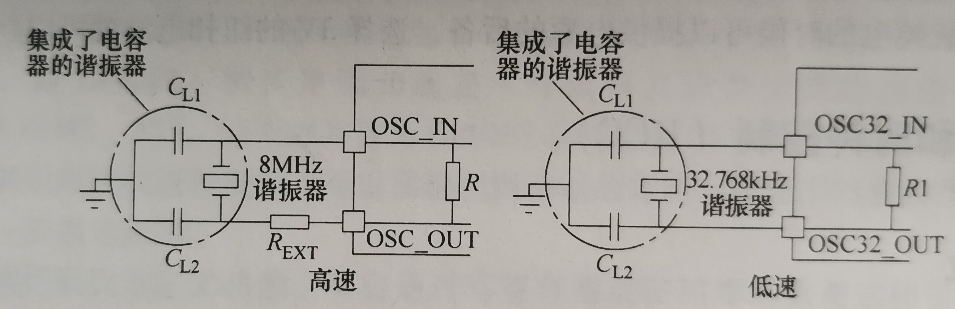
Crystal oscillation circuits are typical, and can be referred to the chip data manual.
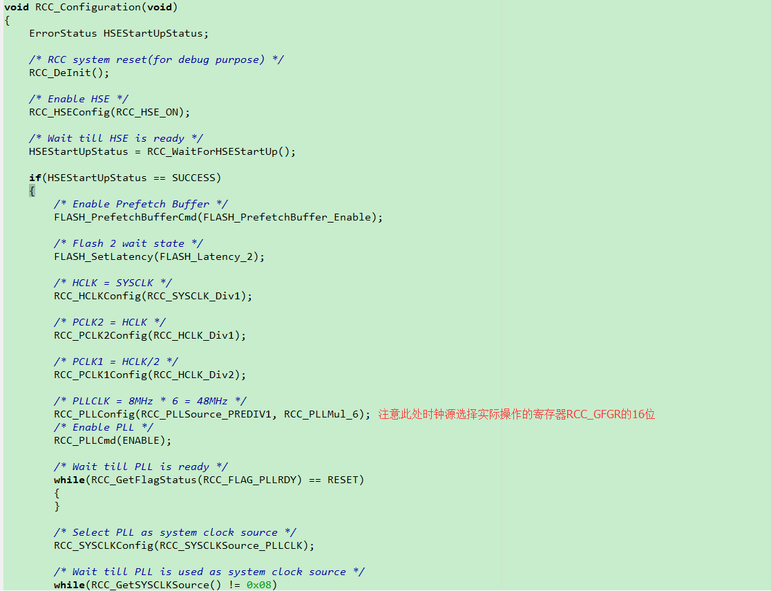
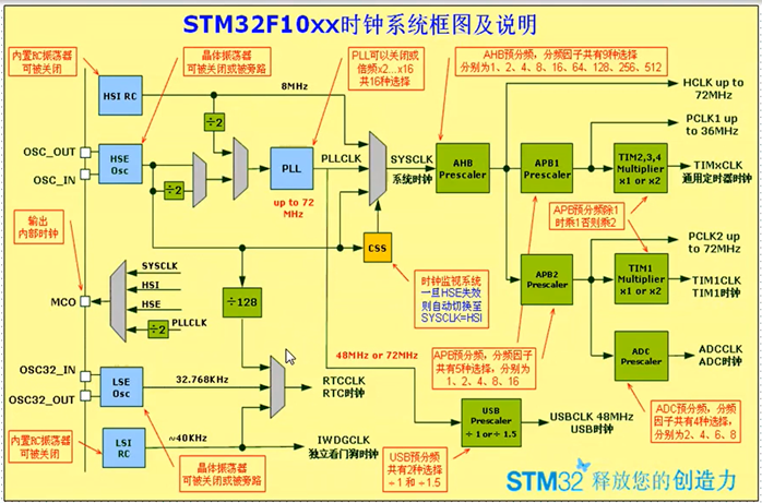
Typically, STM32 is closing at 72 MHz, and the external clock selects 8MHz, so it must be obtained by multiplying. With the PLL, the 8 MHz clock frequency of the external input clock HSE is 9 times, and the clock of 72 MHz can be obtained. The number of times is programmable, and the clock control register can be programmed.
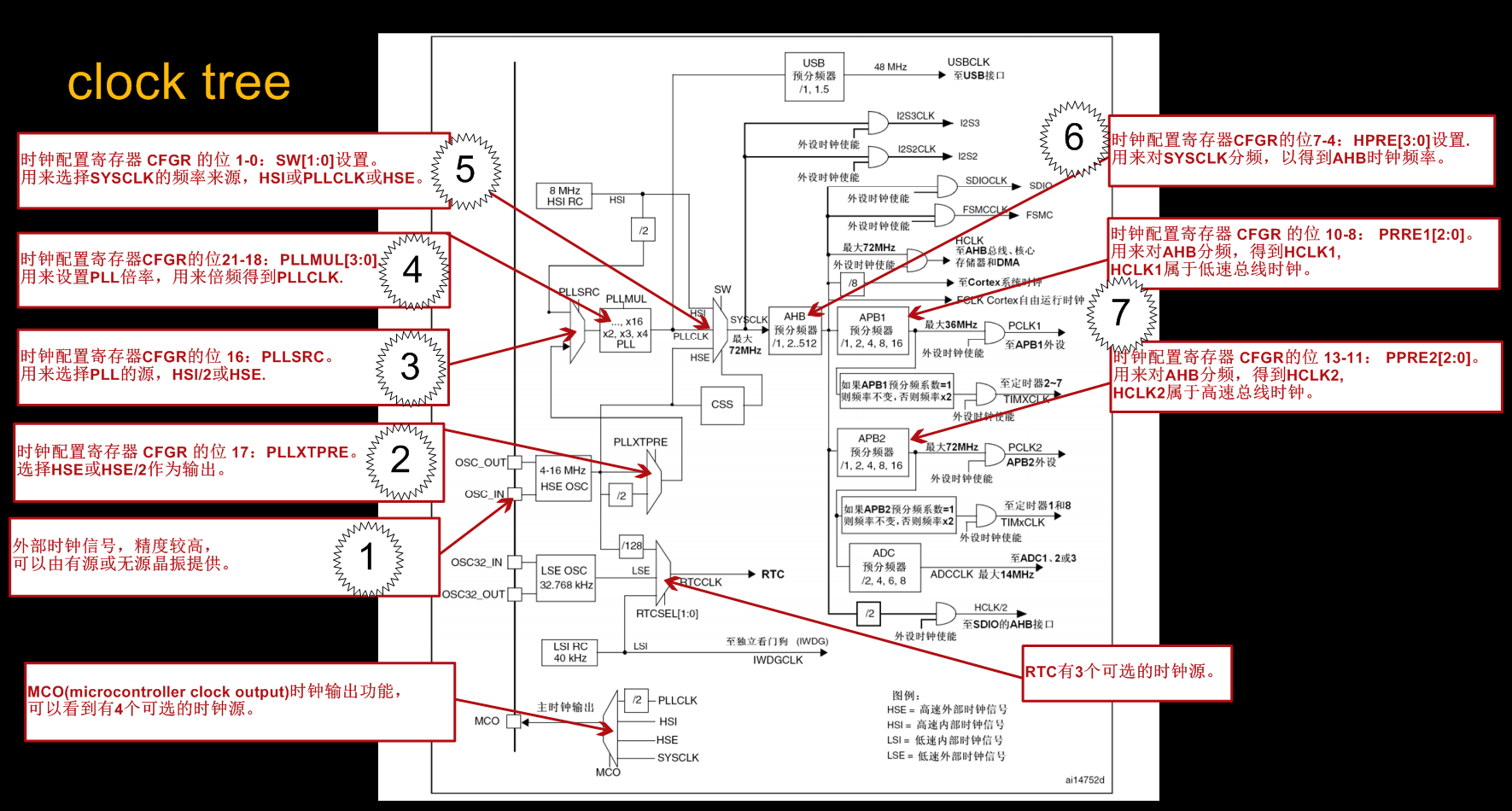
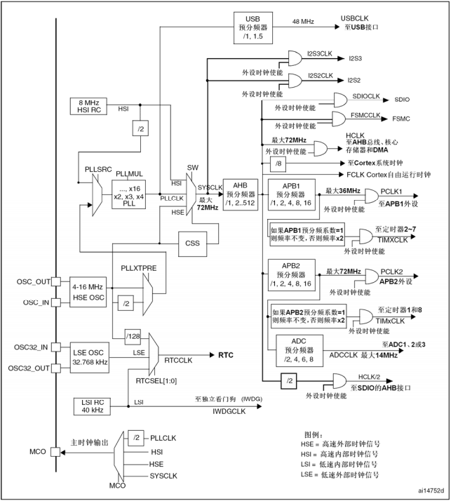
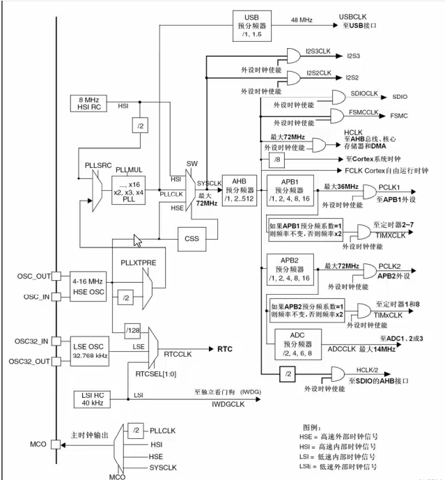
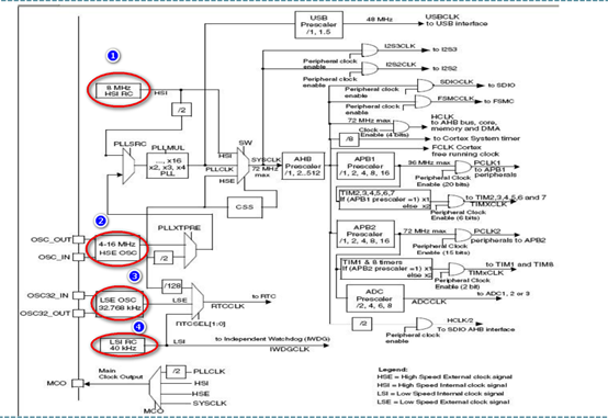
To know the clock of the STM32, you must have aware of the clock tree, as shown in the figure, the clock tree of STM32.

In the clock tree, the input source of the phase-locked loop PLL may be a 2 division or HSE (high speed external clock signal) or HSE 2 division. HSI precision is low, generally select HSE. Typical frequency values are 8 MHz. When the phase-locked loop PLL multiplies the selected clock, the typical frequency value of the input clock is 72MHz, and the PLLCLK all the way is directly sent to the USB pre-propeller generation USB clock: UseCLK (7) another Enter the system clock selector.
The system clock selector selects one as a sysclk (system clock) when the system is reset, but the HSI is low, so the HSI is low, so it is generally written in the clock controller register, so it is generally written by Wrike Clock Controller Register. As the system clock, the HSE multiplier is changed from 72 MHz to PLLCLK, then select PLLCLK as the system clock, then the frequency value of SYSCLK is 72MHz.
SysCLK can be used as a two-way I2S clock through a tanker.
Sysclk performs pre-quadre frequency through the AHB pre-propeller, producing an AHB clock HCLK, which typically sets the prescaler value to 1, which is not divided. Therefore, the HCLK value is generally 72MHz. In the case where the peripheral clock is enabled, the AHB pre-spectrio clock is sent to the AHB bus, called an AHB clock.
When the SDIO clock is enabled, the AHB clock HCLK is selected as an SDIO clock. When the FSMC clock is enabled, the AHB clock HCLK is selected as the FSMC clock.
The AHB clock HCLK was divided by 8 divided into the kernel, which is STCLK, and does not divide the kernel, which is FCLK. The SYSTICK system timer can select STCLK or FCLK for its clock. FCLK is a clock signal for the CPU kernel. The so-called CPU frequency is XXMHz, which means this clock signal, corresponding, reciprocal 1 / fclk is the CPU clock cycle.
APB is a low-speed peripheral bus, AHB clock is divided by APB, a prescaler, generating a low speed clock, and is sent to the APB bus when an APB peripheral is enabled. The APB bus has APB1 and APB2, and there must be two APB pre-propeller. You can set the frequency by setting the frequency. The APB1 clock is PCLK1, and the APB2 clock is PCLK2.
The clock TIMXCLK of Timers 2 to 7 is APB1 clock or twice the same, programmable. The clock TIMXCLK of the timer 1 and the timer 8 is a clock or twice the APB2, which can be programmable. To use the timer 1, you need to open the APB2 clock first, then enable the timer 1 clock; use timer 2, you need to open the APB1 clock first, and then enable the timer 2 clock.
ADC's clock ADCCLK is also divided by APB2. Therefore, use ADC, you need to enable APB2 clock and ADC clock.
HCLK 2 divided SDIO's AHB port.
Real-time clock RTCCLK can be provided by HSE's 128 division, LSE clock or LSI clock.
Watchdog clock IWDGCLK enables internal low speed clock LSI.
The MOC pin can select one of PLLCLK, SYSCLK, HSI, HSE as a clock output.
Through the clock tree, the STM32 clock is very clear, and the selector, divider can be set by programming, to achieve the ideal result. These configuration work can be completed by the configuration of the clock management register, and always manage the register is very important in the system.
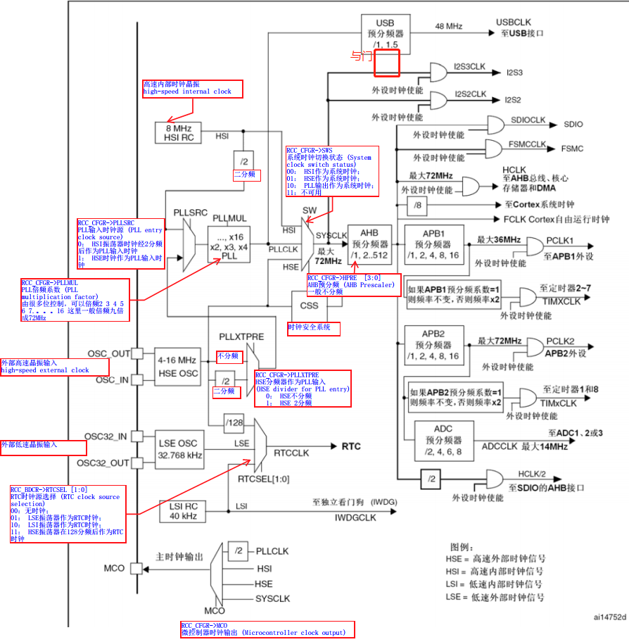
Third, the clock management register
Clock management registers, including clock control registers (RCC_CR), clock configuration registers (RCC_CFGR), clock interrupt registers (RCC_CIR).
The clock control register (RCC_CR) is used to enable external clock and internal clock, enable the PLL function; set the continued flag in various clocks; and configure the calibration of the internal clock and set offsets.
Clock Configuration Register (RCC_CFGR) configures which clock is used as system clock sysclk, and displays which time the middle element is used as system clock; configures the pre-divided frequency of AHB, APB, AD, the clock frequency of AHB, APB, ADC, select PLL The clock source sets its multiplier factor; select the clock source of the STM32 output foot MCO.
Clock Interrupt Register (RCC_CIR) Sets PLL, HSE, HSI, LSE, LSI Ready Interrupt Enable, Clear PLL, HSE, HSI, LSE, LSI Ready Interrupt Sign.
Clock Control Register (RCC_CR), clock configuration register (RCC_CFGR), clock interrupt register (RCC_CIR) See STM32 Reference Manual. The register level is programmed when programming.
Intelligent Recommendation
2. STM32F10X-RCC reset and clock controller
MCU is just like any, its operation needs a pulsating signal to drive, for the single-chip microcomputer, this is the clock controller. The role of resetting the system is to give the microcontroller ...
STM32 clock tree in-depth detailed and RCC configuration
Reprinted address: inSTM32If you do not use an external crystal,OSC_INwithOSC_OUTConnection method If you are using an internal RC oscillator instead of an external crystal, please procee...
Related reference clock RCC STM32 stm32f10x_rcc.h
1. Clock Enable configuration: RCC_LSEConfig()、RCC_HSEConfig()、 RCC_HSICmd()、RCC_LSICmd()、RCC_PLLCmd()...... 2. The clock source configuration: RCC_PLLConfig()、RCC_SYSCLKConfig()、 RCC_RTCCLKConf().......
STM32 RCC register learning-steps to configure the clock
Transfer from: https://www.cnblogs.com/Recca/p/7786967.html There are detailed explanations in , this article only extracts a part RCC (Reset Clock Controller): reset and clock controller 1. Clock The...
STM32 notes (5) RCC clock system
Introduction Due to the powerful performance of STM32, the complex internal composition, and the clock frequency is generally higher than that of 51 single-chip microcomputers, it cannot be simply dep...
More Recommendation
Detailed STM32 system clock RCC workflow
Article Directory Preface 1. Clock tree 2. Work flow 1. Configure the external high-speed clock HSE 2. Configure PLL clock source 3. Configure the PLL multiplication factor to get the PLL clock PLLCLK...
STM32 system clock RCC (based on HAL library)
1. Basic understanding Why have a clock: The clock is the heart of the single-chip microcomputer. Every time it beats, the entire circuit of the single-chip microcomputer will act synchronously. The s...

STM32 F103 RCC uses HSE to configure the clock
STM32F10x Chinese Reference Manual RCC Setting Register H PLL enable and ready flag bit; external high-speed clock HSE enable and ready flag bit; PLLXTPRE: HSE divider as PLL input; PLLSRC: PLL...
Clock Control RCC Application and Detailed Analysis
Clock control RCC Why do you need a clock system? The clock system is like a central nerve, driving all the devices on the chip work at the same time as a specific operating frequency. I think the clo...

STM32 RCC
RCC clock settings Void RCC_Configuration(void){ //Setting the RCC clock ErrorStatus HSEStartUpStatus; RCC_DeInit(); /* RCC system reset(for debug purpose) RCC register restore initializa...