Implementation and Application of EtherCAT - Slave Software and Hardware Design
tags: EtherCAT Application Single chip computer Embedded hardware
01 Slave hardware design
Minimum Slave System
The minimum system of EtherCAT is composed of MCU, ESC, crystal oscillator, EEPROM, PHY chip and RJ45 interface.

Slave application system
Generally speaking, we can use MCU + ESC chips, integrated IO control and motor control two slave solutions. When applying as an IO slave, you can use the on-board 4 LEDs and 4 Buttons to implement the IO logic function. As a Motor slave application, the BLDC motor can be driven using UVW and HALL sampling circuits. In addition, it can also introduce extended interfaces such as ADC, DAC, CAN and RS485.

02 Slave software design
Slave stack code
Code structure
The code structure of EtherCAT Slave Stack Code is shown in the figure below, including ESC memory interface, mailbox (CoE, EoE, etc.), DC (Sync) synchronization function, process data processing, state machine and local communication applications. The processing of process data uses an object dictionary, which is consistent with the definition of the CoE protocol.
The basic sample code is available from the official SSC Tool.
State Machine
The EtherCAT state machine (ESM, EtherCAT Slave Machine) is responsible for coordinating the state relationship between the master and slave applications at initialization and runtime. The ESM in the SSC code is implemented in the AL_ControlInd() function. The EtherCAT device must support four states, and there is an optional state. All state changes are initiated by the master station. For details, you can see the application layer protocol specification of "ETG.1000-part 6".
| name | Abbreviation | describe |
|---|---|---|
| Init | I | initialization |
| Pre-Operational | P | Pre-run |
| Safe-Operational | S | Run safely |
| Operational | O | run |
| Boot-Strap | B | Boot state |

ESI slave information interface file
EEPROM content structure
ESC uses EEPROM to store required device-related information, called Slave Information Interface. The capacity of EEPROM is 1Kbit ~ 4Mbit, depending on the ESC specification. The content structure of EEPROM is shown in the figure below. Use the word address, and the words 0~63 are essential basic information. All of this information is written in the XML file.

XML file structure
Each slave must have an XML configuration file. The object dictionary and PDO settings defined in XML need to correspond to the object dictionary in firmware. Remember the slave information file xml file mentioned in "Overview". Several parts marked with blue are the main configuration content.

The following figure is a view converted by the XML editor. The key object dictionary and data types are in the Devices->Device->Profile element. The above part is manufacturer information, and the following part is slave description information, including device identification, device name, interface type, FMMU channel, SM, process data definition, mailbox, distribution clock, and EEPROM.

Intelligent Recommendation

[STM32 Note 4] UART timing interpretation and hardware application (that is, the implementation of hardware UART, and the use of hardware UART and software UART / hardware serial port and software serial port / USART)
1. Introduction to UART 1、UART(Universal Asynchronous Receiver Transmitter) The bus is an asynchronous serial port, so it is generally much more complicated than the structure of two synchronous seria...
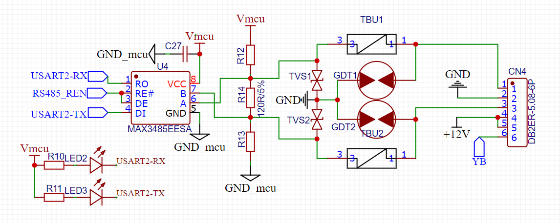
MAX3485 hardware and software design and measurement
MAX3485 principle design and program code TBU selects TUB-CA065-200-WH, GDT selects 2031-23T-SM-RPLF, TVS selects SMBJ6.8CA_C383713, R12, R13 select 3.3K ohm 0603 package, R14 is 120 ohm 1206 package....
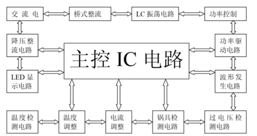
Software and hardware design of induction cooker
The induction cooker is already a quite mature product on the market. Today, the author will talk to everyone's work and control principle. Incurrent cooker induction furnace, one listening, knowing t...

Arduino button software and hardware implementation
It is still an old problem, so the schematic software tool is directly omitted. A schematic diagram is simply hand drawn above, as above. When the Key is pressed and turned on, the acquisition ...
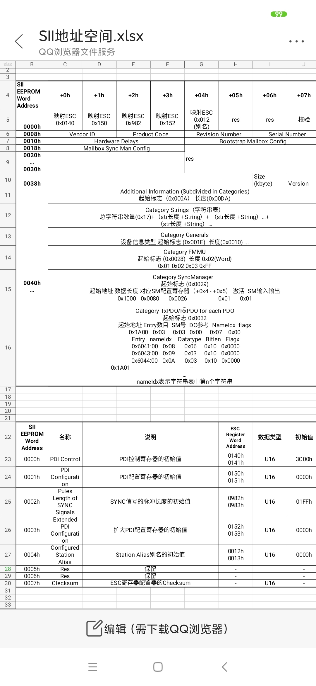
EtherCAT slave SII structure description
EtherCAT slave is abbreviated as ESC. When the ESC is powered on, it will automatically load the first 7 words (1word = 2 byte) in the EEPROM to the ESC register. The ESC register can always be access...
More Recommendation
EtherCAT application layer protocol
No introduction to EtherCAT, only a simple understanding of the EtherCAT application layer protocol 1、COE (CANopen over EtherCAT) A communication protocol based on and fully following the CANopen p...

STM32F103C8T6, FreeModbus slave station design and test (2)-hardware design
Keywords: Modbus FreeModbus STM32F103C8T6 CubeMX With only serial communication, the hardware design is relatively simple. Kong Binghuo (WeChat public account: Kong Binghuo) believes that it can be ro...
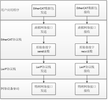
Implementation of EtherCAT on SylixOS
1 Introduction to EtherCAT open source protocol stack At present, the common open source main station codes are SOEM (Simple OpenSource EtherCAT Master) developed by RT-LAB and the IgH EtherCAT Master...
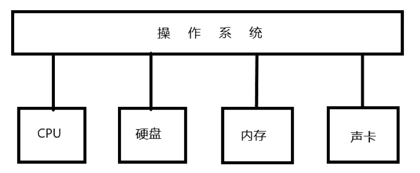
Talking about application software, operating system and hardware
The invention of the computer is to help people complete a very heavy workload In this situation, people naturally act as the largest commander of the computer But the computer can only understand com...
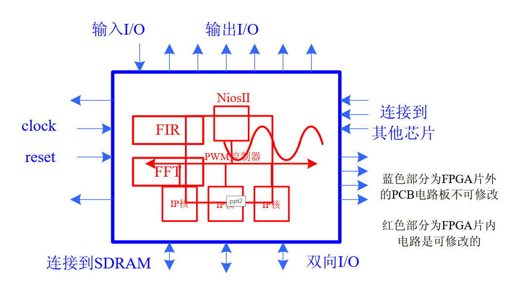
FPGA Learning Embedded Hardware System (SOPC) Overview (Software and Hardware Design)
FPGA Learning Embedded Hardware System (SOPC) Overview (Software and Hardware Design) First, we know that FPGAs can implement logic that acts as a complete microprocessor, and provide many flexibility...