[Original] "1101 Sequence Detector" written in Verilog
tags: fpga/cpld verilog state machine
Sequence detector is one of the very common designs in sequential digital circuits. Its main function isIdentify a specified sequence from the digital code stream. Here is a Verilog implementation and Testbench code of a "1101" sequence detector.
★Design goal: "1101" sequence detector
★EDA:Quartus 15.0
★Simulation software: Modelsim 10.1c
This sequence detector has a total of 4 bits, each bit occupies a state, plus the end state, so the gray code is used to define 5 states:
// Sequence detector status code (Gray code)
localparam	SEQ_IDLE	=	3'b000;
localparam	SEQ_STATE1	=	3'b001;
localparam	SEQ_STATE2	=	3'b011;
localparam	SEQ_STATE3	=	3'b010;
localparam	SEQ_STOP	=	3'b110;
Using a one-stage state machine, the state transition diagram is as follows:
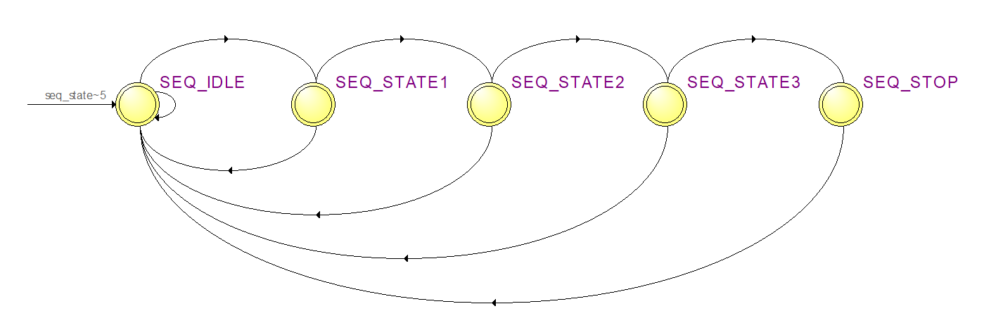
SEQ_IDLE: Check if "1" appears in the bit stream, and jump to the next state if it appears.
SEQ_STATE1: Detect whether “1” appears in the bit stream, jump to the next state if it appears, and jump back to SEQ_IDLE if it appears, and wait for the first “1” bit again.
SEQ_STATE2: Detect whether "0" appears in the bit stream, jump to the next state if it appears, and jump back to SEQ_IDLE if it appears, and wait for the first "1" bit again. To
SEQ_STATE3: Detect whether a "1" appears in the bit stream, jump to the next state if it appears, and jump back to SEQ_IDLE if a "0" appears, wait for the first "1" bit again, and raise the output flag at the same time.
SEQ_STOP: Pull down the output flag bit and jump back to SEQ_IDLE to start the next round of detection.
The complete Verilog code of the "1101" sequence detector is as follows:
module	seq_detector(
 // input port
	 input clk100M, // Input clock: 100MHz
	 input rst_n, // Asynchronous reset: low level reset
	 input data_in, // Input serial data
 // output port
	 output reg data_out // output flag
);


 // Sequence detector status code (Gray code)
localparam	SEQ_IDLE	=	3'b000;
localparam	SEQ_STATE1	=	3'b001;
localparam	SEQ_STATE2	=	3'b011;
localparam	SEQ_STATE3	=	3'b010;
localparam	SEQ_STOP	=	3'b110;


 reg[2:0] seq_state; // status register


 // Sequence detector, one-stage state machine
always@(posedge clk100M or negedge rst_n)begin
	if(!rst_n)begin
		data_out	<=	1'b0;
		seq_state	<= SEQ_IDLE;
	end
	else begin
		case(seq_state)
		 // IDLE detection bit1
			SEQ_IDLE: begin
				data_out		<=	1'b0;
				if(data_in)
					seq_state	<= SEQ_STATE1;
				else
					seq_state	<= SEQ_IDLE;
			end

		 // check bit2
			SEQ_STATE1: begin
				if(data_in)
					seq_state	<= SEQ_STATE2;
				else
					seq_state	<= SEQ_IDLE;
			end

		 // check bit3
			SEQ_STATE2: begin
				if(~data_in)
					seq_state	<= SEQ_STATE3;
				else
					seq_state	<= SEQ_IDLE;
			end

		 // check bit4
			SEQ_STATE3: begin
				if(data_in)begin
					seq_state	<= SEQ_STOP;
					data_out	<=	1'b1;
				end
				else
					seq_state	<= SEQ_IDLE;
			end

		// STOP
			SEQ_STOP: begin
				seq_state	<= SEQ_IDLE;
				data_out	<=	1'b0;
			end
		endcase
	end
end


endmodule
The testbench code is as follows:
`timescale 1ns/1ps
module	seq_detector_tb;

reg			clk100M;
reg			rst_n;
reg[15:0]	        data;
wire			data_in;
wire			data_out;


 // Signal initialization
initial begin
	clk100M   = 0;
	rst_n	  = 1;

	#10 rst_n = 0;
	#10 rst_n = 1;

	 // Generate sequence
	data = 15'b1101_0010_1101_1001;
end


 // Generate 100MHz clock
always
	#5 clk100M = ~clk100M;

 // The sequence is shifted on the falling edge and sampled on the adjacent rising edge
always@(negedge clk100M)
	data = { data[14:0] , data[15] };

 // serial output
assign	data_in = data[15];


 // RTL instantiation
seq_detector seq_detector_inst(
	.clk100M(clk100M),
	.rst_n(rst_n),
	.data_in(data_in),
	.data_out(data_out)
);


endmodule
A 16-bit ring shift register is used in the testbench to move the established 4 groups of 4bit sequences from MSB, bit by bit, from data to data_in and output circularly. If the sequence "1101" is detected, data_out will be raised by one clock cycle.
Intelligent Recommendation
Verilog writes "11010" sequence detector
The sequence detector is one of the very common designs in the timing digital circuit. Its main function isIdentify a specified sequence from the digital code stream. The sequence detector has two mai...
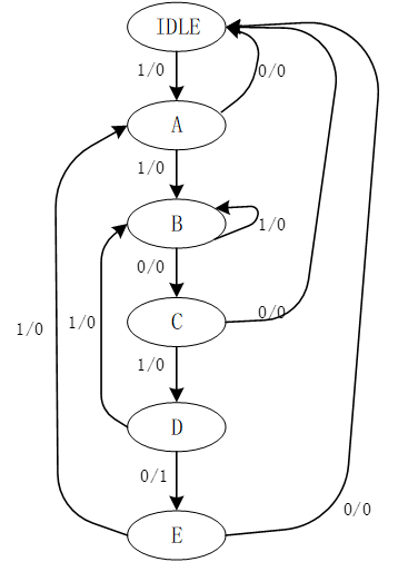
Sequence detector based on System Verilog
This article realizes a 10010 sequence detector through System Verilog Status machine design The state machine is a very important concept in digital circuit design. Many complex controls can be compl...
"reference
Reference is a new language feature introduced by C++. It is one of the important contents commonly used in C++. Correct and flexible use of references can make the program simple and efficient. I fou...
Input.GetAxis(&quot;&quot;) Input.GetAxisRaw(&quot;&quot;)
Input.GetAxis Get axis static function GetAxis (axisName : string) : float Descriptiondescription Returns the value of the virtual axis identified by axisName. Returns the value in the ...
Bean quot
Bean's reference statement First of all, this series of blog refers to the oil pipeSpring Expression LanguageTeaching videoReferencing BeansAnd write. start This episode is a simple look at how to use...
More Recommendation
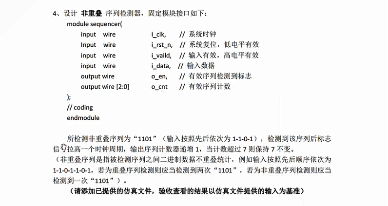
Design and Implementation of 1101 Sequence Detector
module sequencer( input wire i_clk, input wire i_rst_n, ...

Design of verilog-"10101" state machine sequence detector
First, draw a state transition diagram Code: Test code: Simulation results: The more you are, the more you have to work hard....

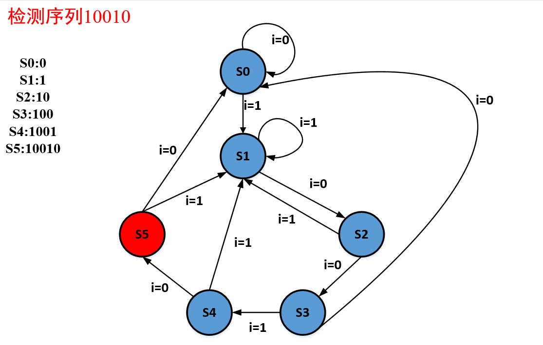
Verilog implementation of "10010" sequence detector and Modelsim simulation
The sequence detector is one of the very common designs in sequential digital circuits. Its main function is to identify a specified sequence from the digital code stream.For example, after receiving ...
Revisit the FPGA sequence detector verilog implementation
1. Title 2. Source code Three-stage state machine 3. Testing platform 4. Simulation waveform ...
Verilog - Sequence Modular Three (Divisible by 3) Detector
Verilog-Sequence Modular Three (Divisible by 3) Detector Description: The input port is 1bit, one bit of data comes in each time, check whether the current sequence can divide 3 evenly, output 1 if it...