Linux kernel 2.4.6 debugging switch chip RTL8364\RTL8367 (uboot debugging)
tags: Work notes linux Embedded arm switch network
platform
Main control chip arm: ast1520
Linux kernel version: 2.4.6
uboot version: 1.1.4
overview
The original main control chip is connected to a phy chip, and the mac controller is connected to the phy chip. The current requirement is to replace the phy chip with the switch chip RTL8367, and use mac to mac connection. That is, the mac controller of the arm is directly connected to the mac port of the switch chip, and the connection speed and connection method are fixed.
analyze
The switching chip supports I2C, SPI, and mdio communication, but the uboot code of ast1520 uses mdio to communicate with the phy chip, so for the time being, the mdio method is used first, and the corresponding pins need to be configured before it can be configured as mdio communication mode. Specific configuration hardware engineers to solve.
Ast1520's uboot has mdio read and write operation commands, which are phyw/phyr
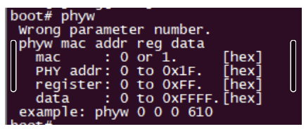
mac indicates whether mac1 or mac2 is used, phy addr indicates phy id, which will be introduced in the chip manual, and the register is the general phy register.
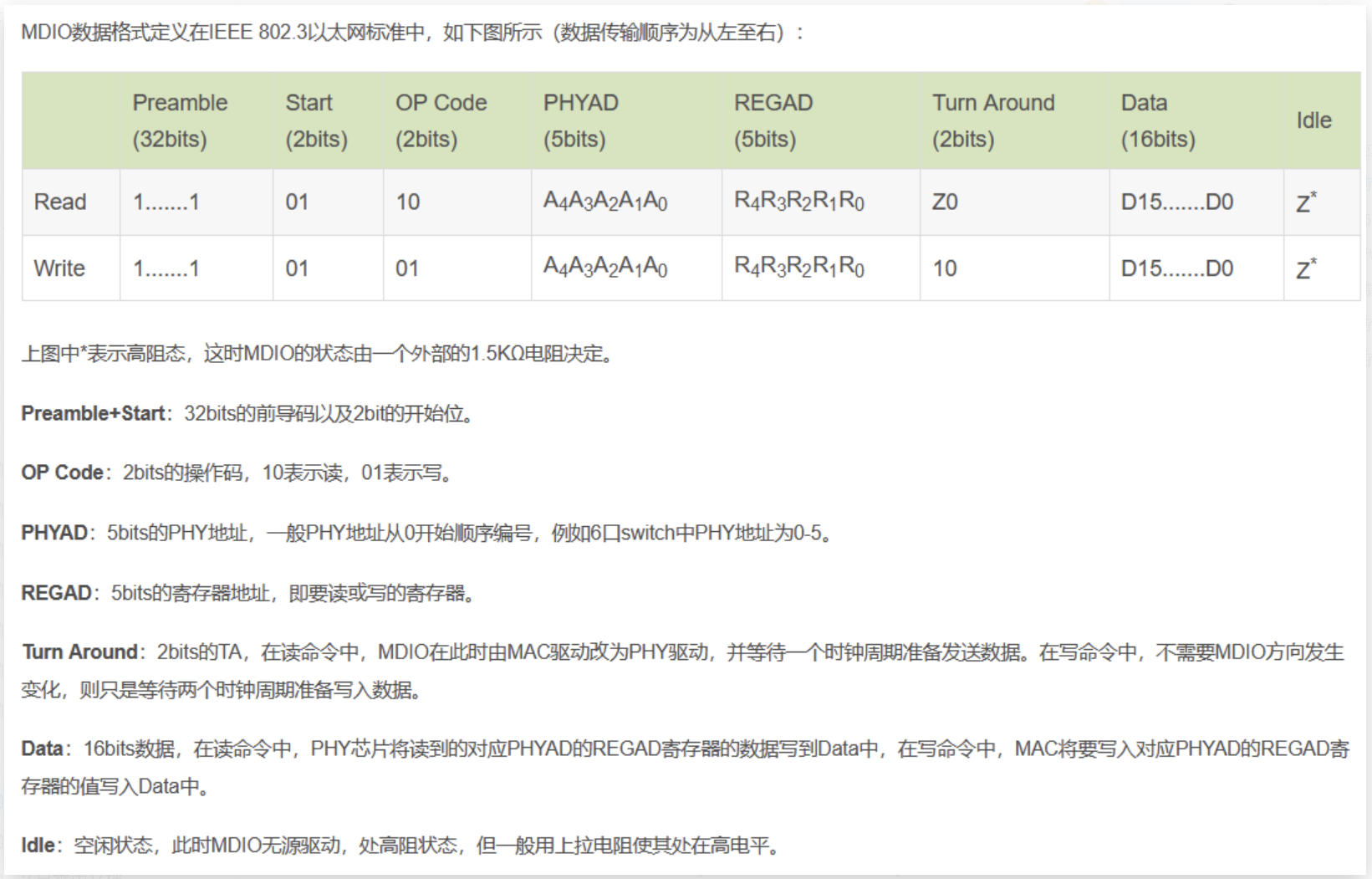
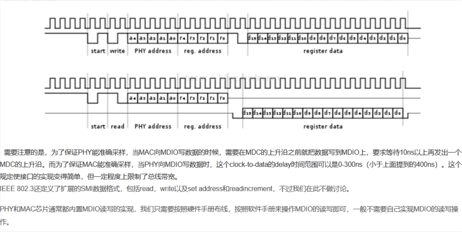
Learn about the mdio protocol
Detailed explanation of RTL8367 switch chip
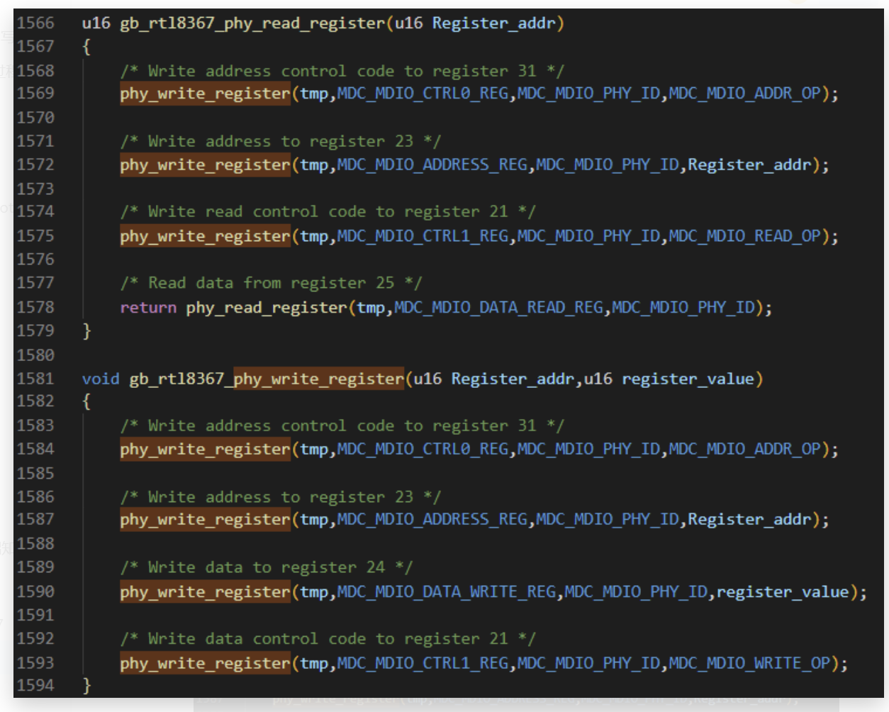
IEEE stipulates that the first 16 registers of all phy chips are common, that is to say, any phy chip can complete basic Internet access functions only by configuring the first 16 registers. The following 16 phy registers are all manufacturer-defined functions. But for the switch chip, because it contains multiple phy chips, that is, utp ports and Gmac ports, there are many configuration options. Generally, switch chips also have their own registers. If you use I2C to access, you can directly Access the address of the register to achieve; if you access through mdio, you need to access the corresponding phy register to indirectly access your own register, such as 8367 is like this:
After transplanting the switch chip code and running it on the board
At present, there is a 125M clock between rtl8367 and ast1520 in both directions, but it still cannot ping the outside network; for the switch chip, you have not configured it, it will have a default register value, and the default register value Those network ports are It works, 8367 is like this. There is no need to configure any of its registers, the default phy port of 8367 is the access.
Because the ast1520 is currently connected to the RTL8367 in the form of flying wires, the flying wires include the mdio connection line and the RGMII connection line. Because the network has high requirements on real-time and timing, if the form of flying line is used, the bit error rate and speed are very different, especially in the gigabit network, it is basically impossible to ping through the form of flying line , so first consider reducing the network speed. RGMII is not only able to run Gigabit networks, it can also run 100M and 10M networks, see the 8367 chip manual
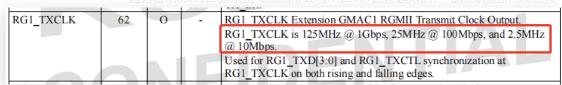
At present, both ends are configured as 10M, and the clock is 2.5Mhz, but it still does not work. The next step is to consider reading the switch chip register.
Question 1: It is configured as 10M communication mode, but the external utp port is not 10M, can it be pinged?
Experiment with the demo board. Well, it is also possible to ping, that is, the ping packet has nothing to do with the network speed; and then found an experimental phenomenon, when using 10M for communication, it is possible to communicate without adding rx_delay and tx_delay, when using a gigabit network When communicating, if rx_delay and tx_delay are not added, there will be problems, probably because the Gigabit communication speed is faster, and the required timing requirements are also higher.
Question 2: Will there be data generated when pinging the packet?
Certainly, measure the data line when the demo board has to exchange the chip ping packet, and the energy can get the corresponding data.
Still can’t ping, what to do, keep thinking
Let’s take a look at the status first. The current situation is that it is configured as a 10M network. Both ends of the clock have been measured, both of which are 2.5Mhz. Logically speaking, there is nothing to set, so we have to measure the corresponding signal data line. , because it is in the form of flying wires, it is very likely that the hardware is not good enough, and it is easy to short circuit.
The data line when measuring the ping packet has data. Of course, I didn’t care what the data looked like. After carefully looking at the data signal, I found that the data line was not pulled low. When I looked at it with the hardware, I found that it was a short circuit when the flying line , resulting in the data line not being pulled low. After modifying the hardware, measure the data line again and find that it is normal.
But the ping is still not working, the egg hurts, and the same configuration is tested on the RTL8364 of the IP5600, and it can be pinged. After thinking for a long time, use the packet capture tool to capture a packet and try it. When I found it, I saw that the main control chip passed The RTL8367 was sent to the computer, and the packet capture tool on the computer captured the ip address of the ast1520, but there was a problem when responding. The computer responded, but the main control chip did not receive it. Communicate with the hardware, measure the signals one by one again, and find that

This pin has no data, that is, there is no fluctuation. Measure the corresponding line of the demo board again and find that this line has data fluctuations, so check the flying line board of ast1520, and finally find that this line is flying wrong, and try again. After a while, it's all right.
Intelligent Recommendation

ftrace debugging Linux kernel
1 Introduction 1.1. ftrace 1.2. Relationship and comparison between ftrace and other trace tools 1.3. Main purpose 2. ftrace kernel compilation options 2.1. Kernel source code compilation options 2.2....
linux kernel deadlock debugging
Use the kernel hacking function of the kernel Open the following configuration: After recompiling the kernel, there will be lockdep lockdep_stats lockdep_chains in the proc directory, indicating that ...
Linux Kernel Testing and Debugging
Linux Kernel Testing and Debugging Jul 10, 2014 By Shuah Khan in debugging kernel Linux PM Sub-system Testing in Simulation Mode The Linux PM sub-system provides five PM test modes to...
Linux kernel dynamic debugging
Dynamic debugging of the kernel The source code uses pr_debug(), pr_info(), pr_err() and other pr_xxx() family printing functions When printing is required (Dynamic debugging), enter the following com...
Linux kernel debugging means
1, NFS command Download the Linux image and device tree in Ubuntu in the Uboot to DRAM, then run directly. That is, network debugging, one of Linux develops most commonly used methods through network ...
More Recommendation
Vscode debugging Linux kernel
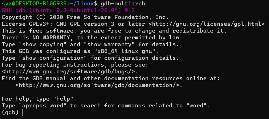
The kernel and GDB are on the virtual machine, in order to view debugging in graphicalization, using VSCode on Windows Current environmental configuration: Host Ubuntu 20.04, Target Aarch64, Kernel 4....
Linux kernel debugging skills
Tips 1: Make Clean After re-make a Linux kernel source code for about 12 minutes; If you don't make Clean, but change the kernel file directly make, although the time spent is small, the changed file ...
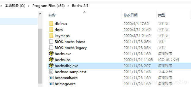
BOCHS debugging Linux kernel
Summary: CMD enters the Bochs installation path runs the following command bochsdbg -q -f bochsrc.bxrc The debug command mainly includes: VBREAK address breakpoint, mating C executes to this address I...
QEMU debugging Linux kernel
1. Open the Linux kernel debugging compilation option make menuconfig 2. Set QEMU boot script parameters Add-S -S command: 3. Download GDB debugging tools 4. Confused Start QEMU script first In anothe...

Linux kernel stack debugging
Linux kernel stack debugging dump_stack Phenomenon reason analyze OOPS information Register information Application layer information Call stack relationship objdump Disassembly Kernel compilation Dis...