The difference between SMBus and I2C
tags: SMBus-i2c
[Turn] The difference between SMBus and I2C
SMbus was first proposed by Intel Corporation. This specification is now managed and maintained by SBS. This specification is simplified by Philips I2C. SMbus is composed of two signal lines. Used for communication between slower devices on the system and power management devices. So that the system can obtain the manufacturer, model, some control information, error information and status of these devices.
The two signal lines are SMBCLK and SMBDATA. This is the same as Clock (SCL) and Data (SDA) on I2C.
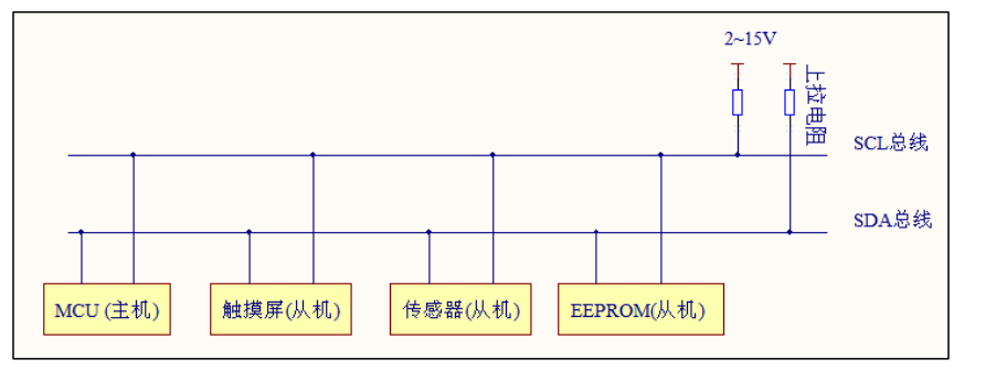
SMbus: Different devices are connected to the same Bus. There is only one Master on SMbus. All commands are issued by this Master. Other devices (Slave) can only receive commands from the Master or reply data to the Master.
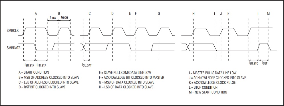
SMbus start and end: When SCL is High and SDA changes from High to Low, it means to start an SMbus command. When SCL is High and SDA changes from Low to High, it means the end of a SMbus command. These two states are unique in Smbus. It is impossible to happen in general data transmission. Generally, the transmitted data is determined by the state of SDA at each rising edge of SCL. These data include arbitration, confirmation, and sending data to a certain device. Or to obtain information about a certain device.
Regarding I2C Bus and SMBus, many people seldom talk about and understand the details of the differences between the two, including many foreign briefing documents often mixing the two, describing them, and using them interchangeably.
Indeed, under general use, there is not much difference between I2C Bus and SMBus, and there is almost no difference from the physical wiring. Even if the two are directly connected, most of them can communicate and operate correctly. However, if you really want to investigate carefully, there are actually many differences. If the electronic design engineer cannot distinguish the real difference between the two, then it will inevitably be troublesome in the verification and debugging phases of future development and design. For this reason, this article will start from all levels. To illustrate the subtle difference between I2C Bus and SMBus, I hope to bring you some help.
Note: For the basics of I2C Bus, please refer to the author’s previous "I2C Interface Circuit Practice", the website is:http://www.digitimes.com.tw/n/article.asp?id=30479 9064272FED148256FDC00481D68
Start with the background of the specification. I2C is an interface created in the design of TV applications. The first version was published in 1992; and SMBus (System Management Bus) is a notebook computer jointly developed by Intel and Duracell (golden top battery). The first version of the interface created by the Smart Battery used was published in 1995. However, it is also mentioned in the SMBus document that SMBus is indeed derived from I2C and based on I2C.
I2C originated in TV design, but then developed towards a general route. Various electronic designs have the opportunity to use I2C; and SMBus is the advanced configuration and power management interface (Advanced Configuration & Power Interface; ACPI) developed for PCs. The management information transfer interface and control transfer interface become the basis of the specification.
Although I2C and SMBus have been formulated at different times, they both entered a mature revision around 2000. The process revision of I2C is mainly aimed at speeding up, while SMBus is more in line with the needs of Smart Battery and ACPI.
▲Illustration: The MAX6641 chip of MAXIM has temperature monitoring and fan control functions (using PWM pulse width modulation to control the fan speed). Pins 7 and 8 in the picture are SMBus (circle), and other devices can be through SMBus Communicate with this chip to obtain temperature and related information, or perform command control. (Picture/MAXIM-IC.com) There are two ways to determine the Hi/Lo logic level of I2C: relative identification and absolute identification. Relative identification is determined by the voltage of Vdd, Hi is 0.7 Vdd, Lo is 0.3 Vdd, absolute Recognition is the same as TTL level recognition, directly specifying Hi/Li voltage, Hi is 3.0V, Lo is 1.5V. The relative SMBus has only absolute identification, and the level is different from I2C, Hi is 2.1V, Lo is 0.8V, which is not completely consistent with I2C but is also considered as a partial intersection. However, SMBus later added a set of lower voltage level identification, Hi is 1.4V, Lo is 0.6V, this is to make devices using SMBus more cost-effective.
After understanding the voltage, it is the current. Since SMBus is used in a notebook computer, the performance of low power consumption is better than I2C. It only needs 100uA to maintain operation, but I2C needs to reach 3mA. The same low power consumption characteristics Reflected in the requirements of leakage current, the maximum leakage current of I2C is 10uA and SMBus is 1uA, but 1uA seems to be too harsh, which makes devices using SMBus cost too much cost and effort during verification and testing. The SMBus 1.1 version relaxes the upper limit of leakage current, up to 5uA.
Furthermore, there are related restrictions. I2C has the limitation of line capacitance, but SMBus does not, but there is also a similar supporting specification, that is, the current limit when the level is pulled down. When the open collector pin of SMBus turns on its gate, When the line is grounded, the current flowing through the ground shall not be higher than 350uA. In addition, the pull-up current (that is, when the same open collector pin is open) is also regulated, the minimum is not less than 100uA, and the maximum is not more than 350uA.
Since there is a limit on the current, it can be easily inferred that the range of the resistance of the boost resistor is required. I2C is greater than 1.6k ohm at 5V Vdd, and greater than 1k ohm at 3V Vdd, and similar SMBus is at 5V Vdd. When it is greater than 14k ohm, 3V Vdd is greater than 8.5k ohm, but this definition is not unbreakable. As far as general practice is concerned, resistance in the range of 2.4k to 3.9k ohm can also be used on SMBus.
Note: The I2C clock line is called SCK or SCL, and the data line is called SDA. The clock line of SMBus is called SMBCLK, and the data line is called SMBDAT.
▲ Caption: I2C and SMBus have different voltage definitions at the logic level. Basically, the definition of I2C is more generous and flexible, while SMBus is more focused on power saving requirements. (Picture/MAXIM-IC.com)
Timing Differences and Tests After the space requirements at the physical level are completed, the time at the physical level comes again, which is the difference in timing (Timing).
First of all, in terms of operating frequency, I2C is quite generous in this respect, the lowest frequency can be 0Hz (DC state, equal to time pause), and the high can be as high as 100kHz (Standard Mode), 400kHz (Fast Mode), or even 3.4MHz (High Speed Mode) , The relative SMBus is very restrictive, the slowest is not slower than 10kHz, the fastest is not faster than 100kHz. Obviously, the intersection operating frequency of I2C and SMBus is between 10kHz and 100kHz.
SMBus used for notebook computer battery management or PC configuration management, power management, it is easy to understand the reason why higher operating frequency is not needed, as long as the supervision information and control command book of small amount of data are transmitted, it does not need to be too high-speed. However, I2C, which is widely used, naturally hopes to use higher transmission to meet various possible needs. However, you may wonder why SMBus has a minimum speed requirement? Why not relax to the same no minimum speed limit as I2C?
SMBus must maintain an operating clock above 10kHz, mainly for management and monitoring. Another intention is that as long as the parameters are added while maintaining a certain transmission speed, it is easy to know whether the bus is currently in Idle. Eliminate the need to detect the STOP signal in the transmission process one by one, or continue to maintain the STOP detection with additional parameter detection, so that it will be more effective and faster to retrieve the bus after it is idle.
After the transmission speed requirement, there is also a data hold time (Data Hold Time) requirement. SMBus stipulates that after the level of the SMBCLK line drops, the data on SMBDAT must be retained for 300nS, but I2C does not have the same mandatory requirement. Similarly, SMBus also has requirements for the recovery time (Timeout) after the interface is reset. Generally speaking, it is 35mS. There is no restriction on I2C, and the time can be extended arbitrarily. The same SMBus also requires that whether it is on the Master or Slave, the longest duration when its clock is at the Lo level must not exceed the limit, so as not to be at the Lo level for a long time. As a result, the timing of the transmitter and receiver is derailed (loss of synchronization, resulting in subsequent malfunctions).
In addition, I2C and SMBus also have different detailed requirements for the rise time and fall time of the level. This point must be confirmed if necessary, or a little attention must be paid during the verification process.
▲Illustration: The realization, supervision, and control of Smart Battery or ACPI requires SMBus (circle) as a backup at the bottom. The picture shows a simple multi-group smart battery system. The picture shows two sets of Smart Battery A and B batteries. . (Photo/SBS-Forum.org)
The compulsory difference between the "completed" and "uncompleted" mechanisms
There are not only electrical and timing differences, but also higher-level agreement mechanisms. In I2C, before the host communicates with the controlled end, it will broadcast the address information of the controlled end on the bus. Each controlled end will receive the address information, but only the recipients that match the address information. After the address information is released, the control terminal will send an "Acknowledge" response (Acknowledge; ACK) to let the control terminal know that the corresponding controlled terminal is indeed ready for communication. However, I2C does not mandate that the controlled end has to respond, and it can also be silent. Even if silent, the host will continue to work, start data transmission and issue read/write commands. Such a mechanism is It is still feasible in general application, but if it is in some real time applications, any action and mechanism have certain time limit requirements. This optional response method will cause problems and may lead to The controlled end cannot receive information.
In the same situation, on SMBus, the controlled end is not allowed to respond after receiving the address information. It must respond every time. Why do I need to force a response? In fact, it is closely related to the application of SMBus. Controlled devices connected to SMBus are sometimes dynamically added or removed, such as replacing a new battery or connecting a laptop to a dock port. If the connected device has been changed If there is no response, the program on the host side does not grasp the latest configuration of the overall system, which will cause malfunction.
A similar situation also applies to ACPI. There are often some devices inside and outside the PC that can be dynamically added or removed, such as internal fans, external printers, etc. These should also be forced to send address information to the host. Give a complete response.
The address operation is different, and the data transmission is also different. In terms of I2C, although the Slave responds to the address sent by the Master, in the subsequent data transmission, the original transmission may not be able to continue due to certain transactions that must be processed in advance. At this time, the Slave will send to the Master The "Not Acknowledge" response (Not Acknowledge; NACK) indicates to the Master that Slave is busy doing his business.
In terms of SMBus, similar to I2C, it will use a NACK response to indicate to the Master that the Slave has not yet received the information delivered, but the SMBus Slave will send a NACK response in each subsequent byte transmission. The reason for this design is Because SMBus has no other representation that can request a resend (Resend) from the Master. To put it more directly, the NACK mechanism is mandatory in the SMBus standard. Any message transmission is very important and no leakage is allowed.
▲Illustration: After I2C completes the transmission of a piece of address or data information, the receiving end can send a message received (ACK) or not (NACK) response. SMBus also has the same mechanism, but there are changes due to the application. Mandatory response request. (Photo/Semiconductors.Philips.com)
Subset and superset of transmission protocol
There is a difference between mandatory or not in the interactive notification mechanism, and the agreement is also different. The SMBus communication protocol and the message format used in the protocol are actually just taken from the subset of the data transmission format definition in the I2C specification. Therefore, if I2C and SMBus are mixed and connected, the I2C device can only use the SMBus protocol and format when accessing the SMBus device. If the I2C standard access method is used, it cannot be accessed correctly.
In addition, there is a general call method called "General Call" in the I2C specification. When the address information of "0000000" is sent out, all the slave devices on the I2C must respond to this. This mechanism is suitable for the Master to respond to All Slaves perform broadcast message updates and communication, which is an overall and batch operation.
SMBus also has a General Call mechanism, but in addition to this, SMBus also has a special ALERT (alert) mechanism, but this must be an additional line (called SMBSUS) outside the clock line and data line. Realization, although ALERT is called a warning, it is actually an interrupt (Interrupt). Slave can pull down the potential of the SMBSUS line (ALERT#, # indicates that the low level is valid), which is equivalent to sending an interrupt warning to the Master Requires Master to provide transmission service for a certain Slave as soon as possible. The Master responds to this service request by communicating through the I2C/SMBus clock line and data line, but how do you know that this communication is only a general communication from Master to Slave? Or is it a service response specifically for Slave's interruption needs?
This is mainly distinguished by the address information sent by the Master. If it is to respond to an interrupted service, the address information must be "0001100". When the Slave receives the address information of "0001100", it knows that this is a special interrupt by the Master. And the service communication provided. Therefore, firmware engineers must pay attention to the fact that during planning, all slaves must not occupy the address "0001100" for the ALERT mechanism (of course! If the ALERT mechanism is not used now and in the future, you can just occupy it). In fact, various advanced specifications (such as Smart Battery, ACCESS.bus, VESA DDC, etc.) have established some addresses reserved for personal use in the short address of I2C, which should have been in the initial design and definition. Pay attention to avoid the trouble of rewriting the firmware in the future due to pre-occupation.
The additional reminder is that SMBSUS is also a circuit with an open collector and a boost resistor, so after a slave pulls down the potential, the other slaves detect that the potential is pulled down, indicating that there is already a slave that is interrupting and responding to the Master. , You must wait for the slave that grabbed the right to interrupt the service to be serviced, and release SMBSUS back to the high level before you can continue to fight for the interruption of the service by "seeing who can lower the line level first?"
Finally, if there are further interested readers, the author suggests that you can refer to two materials:
▲ Picture description: Typical application of MAXIM’s MAX6641 chip. The left side of the picture is the temperature sensing circuit, the upper right is the fan speed control circuit, and the right circle is the SMBus interface circuit. (Picture/MAXIM-IC.com)
Intelligent Recommendation
The difference between SPI, UART, I2C
SPI full duplex synchronization UART full-duplex asynchronous (no clock signal, transfer data by setting baud rate, data bits) I2C half-duplex synchronization The main difference is that when the UART...
The difference between SPI, I2C, and UART
SPI: High-speed synchronous serial port. 3 ~ 4 line interface, send and receive independence, can be synchronously UART: Universal asynchronous serial port. Complete two-way communication according to...
Raspberry Pi installation and I2C tool smbus
smbus I2C module is used to operate the device, to use the I2C function, we first need to install the module installation for the first Raspberry Pi open a terminal and enter the following in it are: ...
I2C (smbus, pmbus) and SPI protocol analysis
I2C and SPI as two very popular low-speed external bus, not new new technology. Some knowledge, understand, not for some time, and they forget. So we decided to take just recently come across these tw...

Raspberry Pi i2c bus usage and i2c-tools python-smbus installation
Write save Open /etc/modules and add i2c-dev, i2c-bcm2708 at the end of the file Write save Update package list once Install i2c-tools tool and python-smbus After rebooting, remember to open the i2c i...
More Recommendation
The difference between SPI, UART, and I2C communication
:https://mp.weixin.qq.com/s?__biz=MzUxMjEyNDgyNw==&mid=2247498262&idx=1&sn=c7d106299976104394e4ce682682747f&chksm=f96b88e2ce1c01f4bddec93439ee8c0adbdb63f5a4afc105ea03ab0a58ba3d48445965...

Raspberry Pi study notes-I2C uses PCF8574 Python SMBUS
1 Introduction The number of GPIO ports of the Raspberry Pi is limited, and the number of GPIOs can be increased through the IO expansion chip, so that the Raspberry Pi can adapt to more applications....

STM32 I2C Slave (SMBUS) Mode Software Reference Design
I2CEveryone is familiar, in total2Root line,CLKwithDATA,stm32ofI2CI believe that everyone will be more familiar with it. The way to write a controller is directly done by the controllerI2CFor sequenti...
Raspberry Pi I2C interface technology and Python SMBus serial I2C EEPROM application programming
Article Directory 1. I2C interface technology 1. I2C bus system composition 2. Status and signal of I2C bus 3. Basic operation of I2C bus 4. Start and stop conditions 5. I2C bus data transmission form...
High-pass LK phase uses analog I2C - Addition I2C Sub Protocol SMBUS-Protocol
When debugging the MIPI conversion chip, you always need to use I2C to initialize it, the Kernel phase is good, and the general Qualcomm platform provides a more complete I2C operation method, just co...