WPF 3D small and small engine - · WPF 3D transformation application
The 3D model that WPF can provide makes it easy to create 3D entities. Although there are still some performance problems at present, it should be desirable for some simple 3D applications. After all, it is highly efficient and easy to use. .
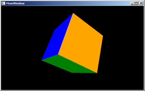
The following is a demonstration of the use of the WPF 3D to achieve the perspective transformation, mouse drag to change the viewing angle, through the wheel to zoom the line of sight.
The basics of 3D can refer to the MSDN documentation: 3D graphics overview
First create a 3D cube, which consists of six faces (F1, F2 ....F6) whose XAML code is as follows:
<Viewport3D>
<Viewport3D.Camera>
<PerspectiveCamera Position="8,8,8" LookDirection="-1 -1 -1" FieldOfView="75" UpDirection="-1 1 -1" x:Name="camera"></PerspectiveCamera>
</Viewport3D.Camera>
<Viewport3D.Children>
<ModelVisual3D x:Name="light">
<ModelVisual3D.Content>
<AmbientLight />
</ModelVisual3D.Content>
</ModelVisual3D>
<ModelVisual3D x:Name="magicCube">
<ModelVisual3D.Content>
<!-- 0: 0,0,0 1: 0,0,2 2: 2,0,2 3: 2,0,0 4: 2,2,0 5: 0,2,0 6: 0,2,2 7: 2,2,2 -->
<Model3DGroup x:Name="cube">
<Model3DGroup.Transform>
<TranslateTransform3D OffsetX="-1" OffsetY="-1" OffsetZ="-1" />
</Model3DGroup.Transform>
<!--F1: 0,3,2,1-->
<GeometryModel3D x:Name="F1">
<GeometryModel3D.Material>
<DiffuseMaterial Brush="Blue"/>
</GeometryModel3D.Material>
<GeometryModel3D.Geometry>
<MeshGeometry3D Positions="0,0,0 2,0,0 2,0,2 0,0,2" TriangleIndices="0,1,2 0,2,3"></MeshGeometry3D>
</GeometryModel3D.Geometry>
</GeometryModel3D>
<!--F2: 0,1,6,5-->
<GeometryModel3D x:Name="F2">
<GeometryModel3D.Material>
<DiffuseMaterial Brush="Green"/>
</GeometryModel3D.Material>
<GeometryModel3D.Geometry>
<MeshGeometry3D Positions="0,0,0 0,0,2 0,2,2 0,2,0" TriangleIndices="0 1 2 0 2 3"></MeshGeometry3D>
</GeometryModel3D.Geometry>
</GeometryModel3D>
<!--F3: 4,5,6,7-->
<GeometryModel3D x:Name="F3">
<GeometryModel3D.Material>
<DiffuseMaterial Brush="Red"/>
</GeometryModel3D.Material>
<GeometryModel3D.Geometry>
<MeshGeometry3D Positions="2,2,0 0,2,0 0,2,2 2,2,2" TriangleIndices="0 1 2 0 2 3"></MeshGeometry3D>
</GeometryModel3D.Geometry>
</GeometryModel3D>
<!--F4: 2,3,4,7-->
<GeometryModel3D x:Name="F4">
<GeometryModel3D.Material>
<DiffuseMaterial Brush="Yellow"/>
</GeometryModel3D.Material>
<GeometryModel3D.Geometry>
<MeshGeometry3D Positions="2,0,2 2,0,0 2,2,0 2,2,2" TriangleIndices="0 1 2 0 2 3" TextureCoordinates="0,0 0,1 1,1 1,0">
</MeshGeometry3D>
</GeometryModel3D.Geometry>
</GeometryModel3D>
<!--F5: 1,2,7,6-->
<GeometryModel3D x:Name="F5">
<GeometryModel3D.Material>
<DiffuseMaterial Brush="White"/>
</GeometryModel3D.Material>
<GeometryModel3D.Geometry>
<MeshGeometry3D Positions=" 0,0,2 2,0,2 2,2,2 0,2,2" TriangleIndices="0 1 2 0 2 3"></MeshGeometry3D>
</GeometryModel3D.Geometry>
</GeometryModel3D>
<!--F6: 0,5,4,3-->
<GeometryModel3D x:Name="F6">
<GeometryModel3D.Material>
<DiffuseMaterial Brush="Orange"/>
</GeometryModel3D.Material>
<GeometryModel3D.Geometry>
<MeshGeometry3D Positions=" 0,0,0 0,2,0 2,2,0 2,0,0" TriangleIndices="0 1 2 0 2 3"></MeshGeometry3D>
</GeometryModel3D.Geometry>
</GeometryModel3D>
</Model3DGroup>
</ModelVisual3D.Content>
</ModelVisual3D>
</Viewport3D.Children>
</Viewport3D>
In the Viewport, six faces are used to form a cube, and each face is a GeometryModel3D.
Here's how to transform the perspective by dragging with the mouse. First add several mouse events to the Window object: MouseMove, MouseLeftButtonDown, and MouseWheel.
<Window x:Class="MagicCube.MainWindow"
xmlns="http://schemas.microsoft.com/winfx/2006/xaml/presentation"
xmlns:x="http://schemas.microsoft.com/winfx/2006/xaml"
Title="MainWindow" Height="295" Width="525" Background="Black"
MouseMove="Viewport3D_MouseMove"
MouseLeftButtonDown="Viewport3D_MouseLeftButtonDown"
MouseWheel="Viewport3D_MouseWheel"
KeyDown="Window_KeyDown">
<Viewport3D …>
</Window>
Explain the few variables used:
MouseLeftButtonDown is used to get the position of the mouse before entering the drag state, so we can change the view according to the change of the mouse position.
Point mouseLastPosition;
private void Viewport3D_MouseLeftButtonDown(object sender, MouseButtonEventArgs e)
{
mouseLastPosition = e.GetPosition(this);
}
Below is the MouseMove event that implements the transformation of the perspective. First of all, in the process of dragging the mouse, horizontal changes and vertical changes may occur, so we will transform different directions of change. Here I have encapsulated the horizontal and vertical transformations into two methods: HorizontalTransform and VerticalTransform.
private void Viewport3D_MouseMove(object sender, MouseEventArgs e)
{
if (Mouse.LeftButton == MouseButtonState.Pressed)
{
Point newMousePosition = e.GetPosition(this);
if (mouseLastPosition.X != newMousePosition.X)
{
HorizontalTransform(mouseLastPosition.X < newMousePosition.X, mouseDeltaFactor);/ / horizontal transformation
}
if (mouseLastPosition.Y != newMousePosition.Y)// change position in the horizontal direction
{
VerticalTransform(mouseLastPosition.Y > newMousePosition.Y, mouseDeltaFactor);//Vertical transformation
}
mouseLastPosition = newMousePosition;
}
}
Next, let's take a look at the concrete implementation of these two transformation methods:
Vertical transformation:
{
Vector3D postion = new Vector3D(camera.Position.X, camera.Position.Y, camera.Position.Z);
Vector3D rotateAxis = Vector3D.CrossProduct(postion, camera.UpDirection);
RotateTransform3D rt3d = new RotateTransform3D();
AxisAngleRotation3D rotate = new AxisAngleRotation3D(rotateAxis, angleDeltaFactor * (upDown ? - 1 : 1 ));
rt3d.Rotation = rotate;
Matrix3D matrix = rt3d.Value;
Point3D newPostition = matrix.Transform(camera.Position);
camera.Position = newPostition;
camera.LookDirection = new Vector3D( - newPostition.X, - newPostition.Y, - newPostition.Z);
// update the up direction
Vector3D newUpDirection = Vector3D.CrossProduct(camera.LookDirection, rotateAxis);
newUpDirection.Normalize();
camera.UpDirection = newUpDirection;
}
private void HorizontalTransform( bool leftRight, double angleDeltaFactor)
{
Vector3D postion = new Vector3D(camera.Position.X, camera.Position.Y, camera.Position.Z);
Vector3D rotateAxis = camera.UpDirection;
RotateTransform3D rt3d = new RotateTransform3D();
AxisAngleRotation3D rotate = new AxisAngleRotation3D(rotateAxis, angleDeltaFactor * (leftRight ? - 1 : 1 ));
rt3d.Rotation = rotate;
Matrix3D matrix = rt3d.Value;
Point3D newPostition = matrix.Transform(camera.Position);
camera.Position = newPostition;
camera.LookDirection = new Vector3D( - newPostition.X, - newPostition.Y, - newPostition.Z);
}
Finally, there is a mouse wheel to adjust the line of sight transformation, as follows:
{
double scaleFactor = 3 ;
// 120 near , -120 far
System.Diagnostics.Debug.WriteLine(e.Delta.ToString());
Point3D currentPosition = camera.Position;
Vector3D lookDirection = camera.LookDirection; // new Vector3D(camera.LookDirection.X, camera.LookDirection.Y, camera.LookDirection.Z);
lookDirection.Normalize();
lookDirection *= scaleFactor;
if (e.Delta == 120 ) // getting near
{
if ((currentPosition.X + lookDirection.X) * currentPosition.X > 0 )
{
currentPosition += lookDirection;
}
}
if (e.Delta == - 120 ) // getting far
{
currentPosition -= lookDirection;
}
Point3DAnimation positionAnimation = new Point3DAnimation();
positionAnimation.BeginTime = new TimeSpan( 0 , 0 , 0 );
positionAnimation.Duration = TimeSpan.FromMilliseconds( 100 );
positionAnimation.To = currentPosition;
positionAnimation.From = camera.Position;
positionAnimation.Completed += new EventHandler(positionAnimation_Completed);
camera.BeginAnimation(PerspectiveCamera.PositionProperty, positionAnimation, HandoffBehavior.Compose);
}
With this small program, if we need to make WPF 3D entities in the future, we can also use it to observe the built 3D entities in 360 degrees.
Demo program Source code
Intelligent Recommendation
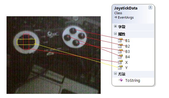
Control the 3D model in WPF with joystick
Original: Control the 3D model in WPF with joystick Control the 3D model in WPF with joystick I feel better today, don't write WF articles, change the theme. Write one of my best content. ...

3d sliding gallery made by wpf
With the popularity and popularity of iphone\ipad, no matter what platform the mobile product is now, the leader always wants to do the imaging ios system. Since Microsoft released the preview of wind...
WPF 3D development tutorial (c)
Three, 3D models 3D model is the object, is the 3D development of the protagonist. We mentioned in the first part, showing the surface using triangulation grid method. The apex of the triangle, each s...

WPF 3D model to join the program
With the computer display to improve the performance of many programs have joined the program has elements of 3D allows more cool results. In fact, the method program to add three-dimensional model ar...
WPF 3D development tutorial (1)
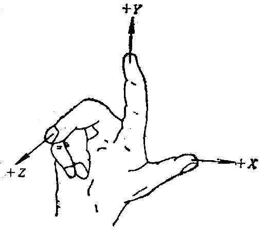
1. Basic knowledge of 3D 1.1 Coordinate system We know that in 2D plane drawing, the coordinate system used by WPF (in fact, the graphics processing on the computer is generally like this) is based on...
More Recommendation
WPF draw a 3D rectangle and rotate
The specific code is still linear algebra. It is mainly rotation and translation. The model in this example was built at the origin of the world. So the rotation will rotate on its own axis. If you do...

WPF drawing 3D animation effect
App.xaml <ResourceDictionary xmlns="http://schemas.microsoft.com/winfx/2006/xaml/presentation" &...

WPF 3D Cube and click interaction
It is easier to build a simple cube in WPF, and there are many reference materials. The more troublesome thing is dealing with click interaction. I implemented 3DCube in WPF in two ways, the effect is...

WPF 3D development tutorial (2)
Second, the camera, light source 2.1 Camera and projection We generally use two kinds of cameras, PerspectiveCamera and OrthographicCamera. PerspectiveCamera: Perspective projection camera, more in li...
Remove aliasing of 3D graphics in WPF
Original:Remove aliasing of 3D graphics in WPF Theoretically speaking, when PC calculates 3D graphics, it is inevitable that there will be no aliasing, because 3D graphics are composed of several tria...